

Electrocoagulation (EC) for (waste) water treatment
1. Theory behind the process
When electric current is applied to Fe plates (the same happens for Al), Fe hydroxide salts (Fe precipitation) are formed in situ due to dissolution of sacrificial Fe (0) anodes. Fe (0) oxidizes to dissolved Fe (II) which then oxidizes further to Fe (III). Water is reduced into hydrogen gas (H2) and hydroxyl ions (OH-) at the cathode, and these hydroxyl ions can combine with the metal ions to form metal hydroxides. The formation rate of these species is directly related to the applied current intensity, as their formation is limited by electron transfer. After their formation, metal ions and metal hydroxides then act as coagulants in the coagulation process. The pH is an important factor in EC treatment, as it determines the speciation of the formed metal ion complexes (Fe(OH)2+, Fe(OH)4- , Fe(OH)3 , Fe2(OH)2 4+), as shown in figure 1.2, and due to their polarity, they attract pollutants. Most of these complexes dissolve poorly into water and will therefore precipitate and withdraw pollutants from the water.
An overview of the reactions that take place in the EC treatment is given in Figure 1.1.
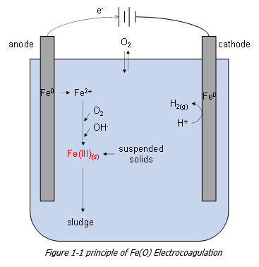
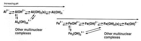
Figure 1‑2 Metal complexes created during Al and Fe electrocoagulation
2. EC advantages
The strength of the technology is the removal of a wide variety of pollutants:
- COD / BOD
- Metal and heavy metal ions
- Suspended solids
- Phosphates
- Colloidal solids
- Coloured compounds
- Dissolved solids
- Surfactants
- Fat, Oil and Grease
- Silica
- Hardness
- Diesel
- Complex organic compounds
- Bacteria and viruses
The advantages of electrocoagulation, in addition to the wide range of pollutants that can be removed, are:
- No extra addition of chemicals
- Less sludge production
- Sludge is easy to dewater (up to 60% DM), without addition of chemicals
- Lower CAPEX and OPEX with respect to classical physical-chemical pre-treatment
- Simple equipment without moving elements
- Colourless and odourless treatment
- Good settling flocs
- Even smallest colloids removed
- Low energy usage
- Sludge separation by simple sedimentation
- Compact construction in container, plug & play
- Low footprint
Depending on the type of wastewater, technology can be implemented in a ZLD system as a:
- Polishing pre-treatment
- Post-treatment
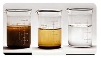
Figure 2‑1 Colour removal with EC
Point of attention
The performance and energy efficiency, while depending on the configuration of the electrocoagulation cell and the connection of the anodes, are also related to the reactions occurring at the electrode–solution interface.
In particular, the formation of passive films or oxides, inhibits dissolution and restricts the charge–transfer reaction at the anode–solution interface and this leads to excessive consumption of electricity and reduces the energy efficiency of the process. Excessive energy consumption, uniformity in dissolution and fouling of the anodes are the main problems that can occurred.
With the EColoRO's know-how, QStone Capital and Lenntech managed to overcome these problems by optimizing the design in terms of hydraulics and electrical solutions.
3. The EC system
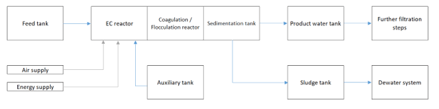
The Electrocoagulation reactor is the reactor that electrochemically treats the wastewater. The treatment will remove the COD/BOD particles, Silica, TSS, Turbidity, Heavy metals, Hardness, partly nitrogen components, phosphate, and colour. All these components will be captured in the coagulation flocs and will be removed from the water by sedimentation or flotation.
Generally, the electrocoagulation unit exists of:
- Screening and neutralization
- EC reactor
- Coagulation tank
- Flotation or sedimentation unit
- Salt/chemical storage vessel + dosing pumps
- Inverters that supply the required current
- External filter press/dewatering system
4. Application
Given the variety of pollutant removal, the EC technology can be applied to the following types of industries:
- Textile
- Pulp and paper
- Automotive
- Chemical and pharmaceutical
- Cosmetics and detergents
- Airports
- Painting
- Solid waste
- Plastic
- Breweries and wineries
- Slaughterhouses
- Domestic and Hotel
- Fruits and vegetables
- Ballast water treatment
- Cooling towers
5. Examples of full systems
The standardized de-centralized systems are based on the flow to treat:
- 25-50 m3/ Day – 20 foot container
- 100-300 m3/ Day – 20 foot container
- 300-500 m3/ Day – 40 foot container
- Higher than 500 m3/ Day – Several 40 foot containers
Example 1. Pilot plant of 1 m3/h
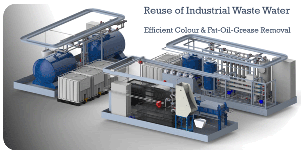
Figure 5‑1 EColoRO pilot
Example 2. Brewery company in Uganda
- Feed: anaerobic effluent
- Capacity: 25 m3/h
- Goal: Phosphates removal
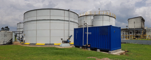
Figure 5‑2 EC system installed in a brewery in Uganda
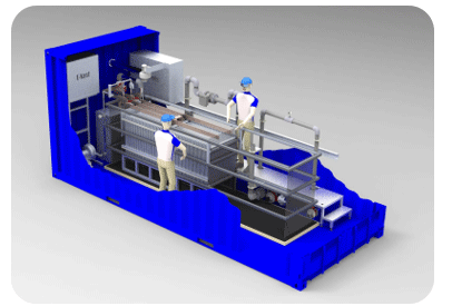
Figure 5‑3 Inside view of the EC system delivered to a brewery in Uganda
Example 3. Industrial solid waste handler in the Netherlands
- Feed: percolate landfill (bottom ash and dredging spoil)
- Capacity: 25 m3/h
- Goal: heavy metal removal
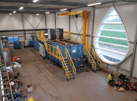
Figure 5‑4 Landfill water treatment facility
Example 4. Industrial solid waste handler in the Netherlands
- Feed: percolate landfill (bottom ash and dredging spoil)
- Capacity: 25 m3/h
- Goal: heavy metal removal
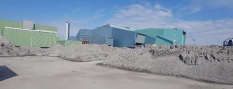
Figure 5‑5 Ashes from solid waste incineration
Example 5. Textile dyeing factory in Tamil Nadu, India
- Feed: Textile dyeing & washing process
- Capacity: 25 m3/h
- Goal: COD, colour, hardness removal
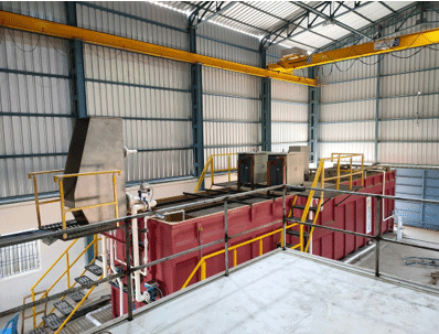
Figure 5‑6 EC system commissioned in India
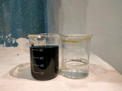
Figure 5‑7 Colour removal in textile wastewater
6. Background history
QStone and EColoRO have been working together on the application of EC in Asia since 2019. When EColoRO unfortunately had to file for bankruptcy in 2020, QStone set up a daughter company QStone EC Water Treatment Solutions with the involvement of the founders of EColoRO and took EColoRO's former senior process engineer on its payroll.
In 2021 QStone EC and Lenntech started co-operating to enhance the further roll-out of EC water treatment technology in Europe and beyond.